The Emergency Measures Radio Group (EMRG) has collected a diverse selection of radios and radio equipment, such as TNCs, phone patches and repeater controllers. The equipment all works well and is used in different applications, depending on its capabilities. In some cases there are several of same model of radio, while in other cases there are only 1 or 2 of a particular model. Every make or model of radio, TNC, phone patch and controller, uses a different connector, or the same connector wired differently. In working with this variety of equipment, it became apparent that a universal connection is required to make it easier to bring equipment together and for rapid replacement in an emergency.
The purpose of standards is to allow equipment to interface together using the same connections and protocols. For radio communications, there are really three things to standardize;
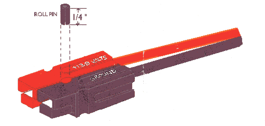
| DC Power Connection | Anderson PowerPole |
|
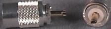
| Antenna Connection | UHF (PL259 - SO239) |
|
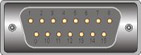
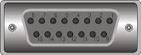
| Audio/Control Connection | DA15 |
|
With these three standards, it becomes very easy to replace a radio if it fails. The same power, antenna and interface connectors are used. The end users will maintain their previous capabilities. This makes the actual radio more transparent to the end users because they don't have to change to a new microphone, etc.
There may be a requirement to change radios for operation on a different band. This could be in a cross-band repeater for example, where the main repeater will accept a link input from a different band. All that is required to change bands, is to change radios and antennas. The existing power supply, antenna cable and repeater interface all wire to standard connectors, so the radio's band capabilities do not matter. This may be required in situations where radios cause interference to other users. These other users may be the same group trying to operate on more than one frequency from the same location, or it could be someone else who operates on VHF frequencies close to the amateur 2 meter band.
Standard User Interfaces can be developed that will plug into the Standard Radio Interface.When talking about people using radios, the typical emergency situation is two people, one as the operator and one as the logger. In order to reduce local noise, each person is wearing a headset. This situation can be enhanced by using either a headset with boom microphone or a desk mike and a separate PTT switch, either hand or foot controlled. While this sounds great, very few, if any amateurs can deliver the setup described. Some may have a headset, but it only allows one person to hear. If they need to share the message over the speaker, they must unplug the headset from the radio. In trying to develop consistent deployment capabilities, it became apparent that a user interface device is required to distribute the radio connections to more than one user.
The first step is defining the physical connection. This includes connector selection and defining the connector pin out. EMRG has selected the DA15 (often incorrectly called a DB15), which looks like a DB25, but with 5 less pins per row. Establishing the physical connection will solve the majority of the issues, which is connecting TNCs or standard user interfaces to radios. Most radios support the same, or close to the same levels and operation, allowing connection to most equipment without any issues. This phase of the standard development has a draft proposal which is out for review.
The physical standard must support as many different types of equipment as possible. This will include VHF/UHF FM radios, HF radios, CB radios, scanners, TNCs, phone patches, wired extensions, wireless extensions, repeater controllers, etc. Each device will support at least some of the connections, while a few radios might support all the connections. Here is the document EMRG-210: Standard Radio Interface.
The second step is defining the electrical parameters for the interface. This includes impedance, signal levels and signal operation. For example, PTT seems easy, but is it normally high, then low to indicate PTT. How high is high and how low is low/ How much current should it sink? While some equipment will work together using the standard radio interface, it may not work at it's best and there are exceptions in some equipment, so it will not work at all. For equipment that does not meet the standard interface electrical parameters, additional circuits will be built into the equipment or into an attached mini box, so that the inputs/outputs at the standard radio interface meet the standard definitions. This phase of the standard development is just starting.
EMRG has already standardized on the DC power connection, by selecting the Anderson Powerpole connector for all DC connections. The standard radio interface is the next step, to allow equipment to be moved and swapped as required. Not all radios will be a replacement for another. There are differences in transmit power, number of channels and ease of programming, but the standard interface maximizes deployment options.
There is very little documentation regarding multi user radio interfaces for Amateur radio. The requirement is often mentioned in articles about using amateur radio for emergency communications. The starting point for the EMRG Standard User Interface, is a UK developed standard called CAIRO, which stands for Communications Audio Interface For Remote Operation. UK Amateurs developed the first standard in the 1980s and did a lot of ongoing development. The CAIRO system is well thought out and provides a great deal of end user capability and flexibility. It is well worth the time to read what was developed and also the reasons that it was developed. The logic behind the development of CAIRO is the same logic driving EMRG to develop the Standard User Interface today.
EMRG will implement the Standard User Interface a bit differently than the UK amateurs with CARIO. The EMRG interface will use the DA15 connector as the main interface, because that will plug into the Standard Radio Interface. While the UK amateurs use of the DIN plugs and jacks was well planned and a good choice at the time, connectors and their use have evolved, so today there are some new de facto standards. For example the speaker jack in almost all radio equipment is a 3.5mm (1/8") mono phone plug. Through the Standard User Interface, EMRG will define the type of connector and wiring for all EMRG interfaces. Individual amateurs can choose to follow the same standard or build an interface between their equipment and the EMRG standard.
The purpose of a Standard Radio Interface is to allow more than one operator to access a radio. The operators could be sitting side by side, using one interface box with jacks for 2 users, or the two operators could be separated by an interconnection cable. The Standard User Interface must allow for connection of more than one user location to the same radio.
Development of the Standard User Interface is just starting. Check out the Standard User Interface page for the latest ideas and drawings.